Overview
I had a lot of fun at GrrCON last month. It was refreshing to be surrounded by passionate folks who had their own individual reasons to remain in the weeds. Kyle Meyer's talk on malware generation in seven minutes, as well as f8al's car hacking adventure, both played a role in reigniting the fun of hardware hacking.
I relegated this range extender some time last year. They never do truly work as they should: the roaming sucks, they're not seamless on the net, and they're easily exploitable. This post won't be a how-to on remote attacking the device or utilizing any exploits. The intent is to demonstrate an approach for cracking open devices and getting connected. Here, we will do that via UART, as well as dumping firmware off of the SPI chip. If you have old hardware laying around, you should hack it.
Artifacts
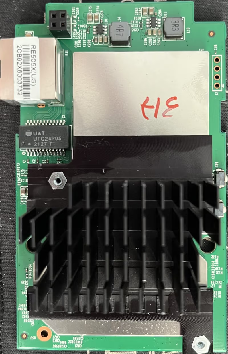
Looking at the top of the device PCB (the RE505X for this case), the majority of it is taken up by a heat sink that sits over the SOC. In the top right interface, we can see the UART debug port. Short of this being explicitly labeled with VCC, GND, RX, and TX on its pins, it's a clear indicator that this is UART. This is a good starting point for poking around.
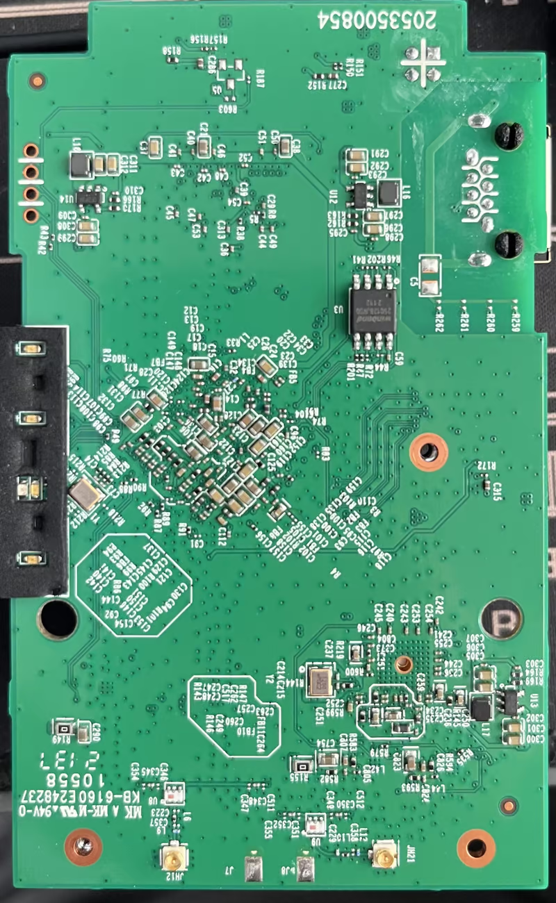
Not much else on the bottom of the board for our case—we see our UART on the left now. Our other piece of interest is the SOIC8 SPI flash chip on the right. This houses a filesystem, tells the system what to do on boot, and handles (on some devices) things like local web servers, dropbear, and credentials. Some of these are more common on IoT devices than others.
We can also refer to FCC documents for more photos. In some cases for more involved boards, this is a good recon approach. For the RE505X we can use:
It's worth noting that the FCC and chip manufacturers have put data sheets behind validation or captcha. This unfortunately makes it more difficult to automatically scrape these documents with a script or other metadata. Having the FCC resources on hand will help give a more holistic understanding of the device (the RE505X is pretty small, in our case here, so there's not much to miss).
Bill of Materials
We'll need at minimum a way to interface with the device. There's many options available but to get off the ground quickly:
- FT232/H or another UART to USB interface
- Some jumper wires
- A SOIC8 clip if you want to dump firmware off of flash
- Pyftdi for firmware dumping (there's other binaries too)
- Binwalk to extract the dumped firmware.bin files
- A voltmeter (unless you're lucky)
- Some patience
Finding UART
Sometimes you get lucky and the UART interface is labeled, maybe even some pin headers soldered on. Here's another board that has a touch more detail than our RE505X.
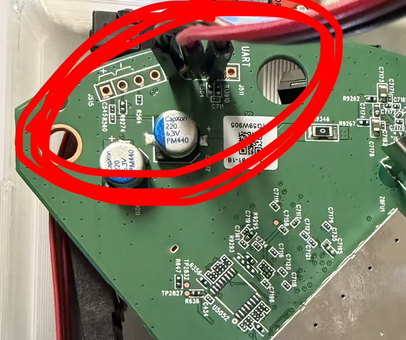
In most cases, the VCC or GND pin will be on one of the ends. To avoid the risk of frying your board, however, you should verify this with a voltmeter. An easy way to start is to have the device powered off. Put the voltmeter in continuity mode and put one lead on a shield. In the case of the RE505X you could use the ethernet module housing. With the other lead, probe each of the four headers until you get a beep feedback, which indicates continuity. Power on the device, switch the voltmeter to DC voltage, and probe. One lead should be grounded, and the other should check the headers.
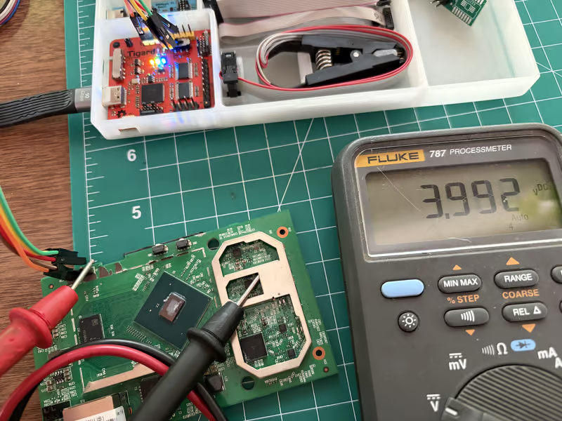
A steady 1.8/3.3/5V will either indicate VCC or RX. A fluctation of voltage typically indicates the TX pin. A reliable bet would be to assume the RX pin is next to TX, which leaves the remainder as the VCC. The device should be wired up to your UART interface as follows:
| Device (RE505X) | Interface |
|---|---|
| VCC | VCC |
| GND | GND |
| RX | TX |
| TX | RX |
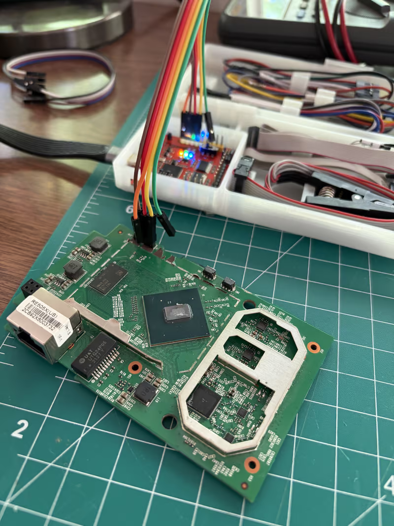
At this point, short of needing to swap the RX/TX wires if you don't see data, you should be all set. Plug in the interface into your computer.
Getting UART Output
You can use something like screen or minicom for this, but I typically use picocom. You'll need the baud rate for the device. If you don't know it, you can guess: 9600 and 115200 are very common. If you get gibberish, you're probably on the wrong baud. You can use a logic analyzer to find the rate. I plan on detailing this in another post.
Start picocom once you're plugged in:
picocom -b 115200 --imap lfcrlf /dev/ttyUSB0You might be under a different device than /dev/ttyUSB0, so ls /dev if you aren't getting output, and find out what your interface is mounted as. The input mapping arg lfcrlf makes the output less hellish and readable, salt to taste. If all is well, you'll start seeing the device boot:
----
BTRM
V1.1
CACH
CODE
ZBSS
MAIN
OTP?
OTPP
USBT
SNOR
IMG?
IMGL
UHD?
UHDP
RLO?
RLOP
UBI?
UBIP
PASS
----
BTRM
V1.1
CACH
CODE
ZBSS
MAIN
OTP?
OTPP
USBT
SNOR
IMG?
IMGL
UHD?
UHDP
RLO?
RLOP
UBI?
UBIP
PASS
----
BTRM
V1.1
CACH
CODE
ZBSS
MAIN
OTP?
OTPP
USBT
SNOR
IMG?
IMGL
UHD?
UHDP
RLO?
----
BTRM
V1.1
CACH
CODE
ZBSS
MAIN
OTP?
OTPP
USBT
SNOR
IMG?
IMGL
UHD?
UHDP
RLO?
RLOP
UBI?
UBIP
PASS
HELO
CPU0
L1CD
MMUI
ZBBS
MAIN
5.0207test9-1.0.38-163.212
Boot Strap Register:  0x7fffffff
Applying trim code 0x1 reg 0x4 from otp to LDO controller...
NVRAM memcfg 0x20000327
MCB chksum 0x86e6dff2, config 0x20000327

MemsysInit lpf0fc_generic 3.3.7.100 20180907
DDR3
84217B5C 80180000 801A0000 00000000 00000000 00605997
MCB rev=0x00060301 Ref ID=0x05997 Sub Bld=0x006
Dram Timing 11-11-11

start of memsys_begin
mc_cfg_init(): Initialize the default values on mc_cfg
init_memc_dram_profile(): Initializing MEMC DRAM profile
---------------------------------------------------------------
MEMC DRAM profile (memc_dram_profile_struct) values:
  dram_type    = DDR3
====================================================
PART values:
  part_speed_grade    = 1600 CL11
  part_size_Mbits     = 2048 (DRAM size in MegaBits)
  part_row_bits       = 14 (number of row bits)
  part_col_bits       = 10 (number of column bits)
  part_ba_bits        = 3 (number of bank bits)
  part_width_bits     = 16 (DRAM width in bits)
NUMER OF PARTS:
  part_num            = 1 (Number of parts)
TOTAL values:
  total_size_Mbits    = 2048 (DRAM size in MegaBits)
  total_cs_bits       = 0 (number of cs bits, for dual_rank mode)
  total_width_bits    = 16 (DRAM width in bits)
  total_burst_bytes   = 16 (Number of bytes per DRAM access)
  total_max_byte_addr = 0xfffffff (Maximum/last DRAM byte address)
                        (Number of bits in total_max_byte_addr is 28)
                        (i.e. total_max_byte_addr goes from bit 0 to bit 27)
  ddr_2T_mode         = 1
  ddr_hdp_mode        = 0
  large_page          = 1
  ddr_dual_rank       = 0
  cs_mode             = 0
MEMC timing (memc_dram_timing_cfg_struct) values:
====================================================
  MC_CHN_TIM_TIM1_0 register fields:
    tCwl   = 8
    tRP    = 11
    tCL    = 11
    tRCD   = 11
  MC_CHN_TIM_TIM1_1 register fields:
    tCCD_L = 4
    tCCD   = 4
    tRRD_L = 6
    tRRD   = 6
  MC_CHN_TIM_TIM1_2 register fields:
    tFAW   = 32
    tRTP   = 6
    tRCr   = 39
  MC_CHN_TIM_TIM1_3 register fields:
    tWTR_L = 6
    tWTR   = 6
    tWR_L  = 12
    tWR    = 12
  MC_CHN_TIM_TIM2 register fields:
    tR2R   = 0
    tR2W   = 2
    tW2R   = 2
    tW2W   = 0
    tAL    = 0
    tRFC   = 128
====================================================

Poll PHY Status register
PHY Status= 1
Disable Auto-Refresh
[0x80180200] = 0x00000305
End of memsys_begin
Add/Ctl Alignment
no adjustment
Base: 5.2_07test9
CFE version 1.0.38-163.212 for BCM963178 (32bit,SP,LE)
Build Date: Tue May 11 17:42:29 CST 2021 (jenkins@Sohoiipf)
Copyright (C) 2000-2015 Broadcom Corporation.
Boot Strap Register: 0x7fffffff
Chip ID: BCM6750_A2, ARM Cortex A7 Triple Core: 1500MHz
Total Memory: 268435456 bytes (256MB)
HS Serial flash device: ID_W25X128, id 0x0000ef18 sector 64KB size 16384KB
Flash split 96 : AuxFS[393216]
Take PMC out of reset
waiting for PMC finish booting
PMC rev: 3.0.8.223958 running
pmc_init:PMC using DQM mode
close avs with [island 0] margin_mv slow 100 fast 60 [max_mv 0 min_mv 0 (0 means using firmware default)] succeeded
Board IP address : 192.168.1.1:ffffff00
Host IP address : 192.168.1.100
Gateway IP address :
Run from flash/host/tftp (f/h/c) : f
Default host run file name : vmlinux
Default host flash file name : bcm963xx_fs_kernel
Boot delay (0-9 seconds) : 1
Default host ramdisk file name :
Default ramdisk store address :
Default DTB file name :
Board Id : TP6750
Number of MAC Addresses (1-64) : 11
Base MAC Address : 02:10:18:01:00:01
PSI Size (1-512) KBytes : 48
Enable Backup PSI [0|1] : 0
System Log Size (0-256) KBytes : 0
Auxillary FS Size(uint 4KB) : 96
WLan Feature : 0x00Once the filesystem is established (if there is one), default configs start being set.
init procfs
nf_conntrack version 0.5.0 (3970 buckets, 15880 max)
NET: Registered protocol family 17
bridge: automatic filtering via arp/ip/ip6tables has been deprecated. Update your scripts to load br_netfilter if you need this.
8021q: 802.1Q VLAN Support v1.8
Registering SWP/SWPB emulation handler
VFS: Mounted root (squashfs filesystem) readonly on device 31:0.
devtmpfs: mounted
Freeing unused kernel memory: 160K
procd: Console is alive
procd: - preinit -
Mounting filesystems...
mkdir: can't create directory '/dev/pts': File exists
mount: mounting devpts on /dev/pts failed: Device or resource busy
>>>>> Starting mdev <<<<<
>>>>> Creating static device nodes <<<<<
>>>>> Mounting /data partition <<<<<
>>>>> Mounting data partition as JFFS2 <<<<<
Configuring system...
kmod: insmod: argv[1]:/lib/modulwlcsm: module license 'Proprietary' taints kernel.
es/4.1.52/extra/wlcsm.ko, argv[0Disabling lock debugging due to kernel taint
]: insmod
kmod: module_path: /lib/modules/4.1.5Initializing WLCSM Module
2/extra/wlcsm.ko
kmod: Insmod: WLCSM Module loaded successfully
/lib/modules/4.1.52/extra/wlcsm.ko
restore done!
*** populated ***
is_nand:0  is_manufacturer:0
Loading drivers and kernel modules...

kmod: insmod: argv[1]:/lib/modulBCMLIBS loaded...
es/4.1.52/extra/bcmlibs.ko, argv[0]: insmod
kmod: module_path: /lib/modules/4.1.52/extra/bcmlibs.ko
kmod: Insmbrcmchipinfo: brcm_chipinfo_init entry
od: /lib/modules/4.1.52/extra/bcmlibs.ko
kmod: insmod: argv[1]:/lib/modules/4.1Broadcom Ingress QoS Module  Char Driver v1.0 Registered<303>
.52/extra/wlcsm.ko, argv[0]: ins
Broadcom Ingress QoS v1.0 initialized
mod
kmod: module is already loaded - wlcsm
kmod: insmod: argv[1]:/lib/modules/4.1.52/extra/chipinfo.ko, argv[0Broadcom Packet Flow Cache
]: insmod
kmod: module_path: /lFCACHE_CONFIG_MAX_FLOW_ENTRIES<16384>
ib/modules/4.1.52/extra/chipinfoFCACHE_CONFIG_MAX_FDB_ENTRIES<1024>
.ko
If output is clean, you can re-run picocom with the --logfile arg to dump the boot to a file for forensics e.g.
picocom -b 115200 --imap lfcrlf /dev/ttyUSB0 --logfile uart-boot.logKeep your eyes peeled, you might find some interesting bits:
VFS: Mounted root (squashfs filesystem) readonly on device 31:0.
...
>>>>> Starting mdev <<<<<
>>>>> Creating static device nodes <<<<<
>>>>> Mounting /data partition <<<<<
>>>>> Mounting data partition as JFFS2 <<<<<
...
DROPBEAR_PASSWORD='' dbclient -y root@127.0.0.1 id; echo "exit=$
?"
We can see above that a read-only squashfs filesystem gets mounted, we can dig this up from the SPI firmware later. We also see a JFFS2 partition, which is writable flash memory. And finally a dropbear ssh server with.. an empty password.
Until we're finally dropped into a root shell running OpenWRT:
BusyBox v1.22.1 (2021-05-11 18:01:23 CST) built-in shell (ash)
Enter 'help' for a list of built-in commands.

     MM           NM                    MMMMMMM          M       M
   $MMMMM        MMMMM                MMMMMMMMMMM      MMM     MMM
  MMMMMMMM     MM MMMMM.              MMMMM:MMMMMM:   MMMM   MMMMM
MMMM= MMMMMM  MMM   MMMM       MMMMM   MMMM  MMMMMM   MMMM  MMMMM'
MMMM=  MMMMM MMMM    MM       MMMMM    MMMM    MMMM   MMMMNMMMMM
MMMM=   MMMM  MMMMM          MMMMM     MMMM    MMMM   MMMMMMMM
MMMM=   MMMM   MMMMMM       MMMMM      MMMM    MMMM   MMMMMMMMM
MMMM=   MMMM     MMMMM,    NMMMMMMMM   MMMM    MMMM   MMMMMMMMMMM
MMMM=   MMMM      MMMMMM   MMMMMMMM    MMMM    MMMM   MMMM  MMMMMM
MMMM=   MMMM   MM    MMMM    MMMM      MMMM    MMMM   MMMM    MMMM
MMMM$ ,MMMMM  MMMMM  MMMM    MMM       MMMM   MMMMM   MMMM    MMMM
  MMMMMMM:      MMMMMMM     M         MMMMMMMMMMMM  MMMMMMM MMMMMMM
    MMMMMM       MMMMN     M           MMMMMMMMM      MMMM    MMMM
     MMMM          M                    MMMMMMM        M       M
       M
 ---------------------------------------------------------------
   For those about to rock... (Attitude Adjustment, r2611)
 ---------------------------------------------------------------
root@OpenWrt:/#
It's interesting when a proprietary device rolls OpenWRT and configures it poorly. For this device, getting root shell is almost unrewarding. It's about as straight forward as you can get. At this point, we can start looking for things that will make us depressed. Here's a gist of items found via UART on this device thanks to the root shell.
/etc/shadow contains root::0:0:99999:7:::. With the second field empty, the root account has no password hash. The /etc/config/dropbear config sets RootPasswordAuth 'on' as well as PasswordAuth 'on'. This gives instant root on any login path that accepts a blank password.
/etc/config/accountmgnt has a full RSA key pair:
root@OpenWrt:/# cat /etc/config/accountmgnt

config rsa 'keys'
    option e '010001'
    option d '091550E28B45A770B296EDAEEF04E687F3258AB765A22E7CEA9D1BC8EB10BD2A0601A4421D267FD5ED5BF25A7372B67FFAD6D41A81A194B67623617F0A86A28F3727A6EC0E34ACCA4823F486CB3E08D9BBC2D043D62CC943EF898EF7C74CDCD8E9CEA87006019D6464B7B2BA37043D911611580A7A87D862E6BEBE4AD96146B1'
    option n 'D1E79FF135D14E342D76185C23024E6DEAD4D6EC2C317A526C811E83538EA4E5ED8E1B0EEE5CE26E3C1B6A5F1FE11FA804F28B7E8821CA90AFA5B2F300DF99FDA27C9D2131E031EA11463C47944C05005EF4C1CE932D7F4A87C7563581D9F27F0C305023FCE94997EC7D790696E784357ED803A610EBB71B12A8BE5936429BFD'
and by running mount we can see the filesystem layout:
root@OpenWrt:/# mount
/dev/root on / type squashfs (ro,relatime)
devtmpfs on /dev type devtmpfs (rw,relatime,mode=0755)
proc on /proc type proc (rw,noatime)
sysfs on /sys type sysfs (rw,noatime)
tmpfs on /var type tmpfs (rw,relatime,size=420k)
tmpfs on /mnt type tmpfs (rw,relatime,size=16k,mode=0755)
mtd:data on /data type jffs2 (rw,relatime)
none on /etc type ramfs (rw,relatime)
none on /usr/lib/lua type ramfs (rw,relatime)
tmpfs on /dev type tmpfs (rw,relatime,mode=0755,size=512K)
devpts on /dev/pts type devpts (rw,relatime,mode=600)
These are good clues for our next task, which is dumping the SPI firmware. This will give us the ability to even change and flash a new binary, if we wanted to.
SPI
You'll need some SPI headers on your interface, a SOIC8 clip, or eight jumper wires and a dream, to get connected up to the SPI flash. Clip is an easy option as long as you get a good connection. Make sure to line up the red wire with the correct pin. This is usually denote by a circle on the chip.
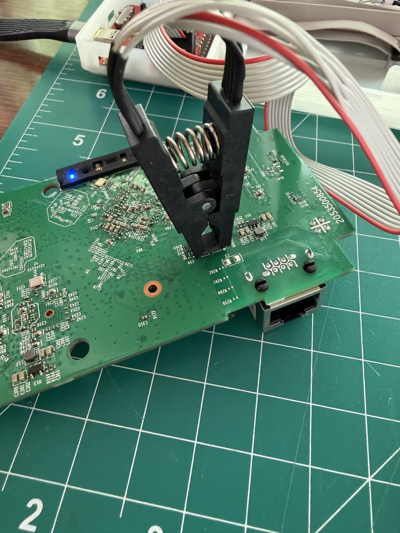
It's helpful to dig up the chip data sheet if you're going this route. Here's ours, it shows the pin mapping:
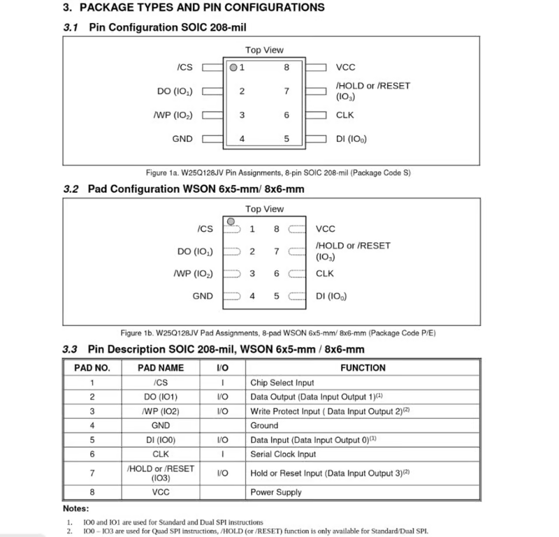
CS in our case is where the red wire should align. This data sheet doesn't give us anything notable we need to worry about. Some chips will require certain pins to be held high, or low, which can impact the ease of just hooking up to the SPI and dumping firmware. That doesn't apply to us here, so it's a straight forward read.
Firmware Extraction
I use a perl script for this, to do some housekeeping and verification around the firmware dump integrity. We're simply calling the pyftdi lib to get a clean JEDEC ID, determine the manufacturer, set the frequency, and start extraction:
my $dump_code = <<'PY';
    import sys
    from pyftdi.spi import SpiController
    out  = sys.argv[1]
    size = int(sys.argv[2])
    freq = int(sys.argv[3])
    ctrl = SpiController()
    ctrl.configure('ftdi://ftdi:2232h/2')
    spi = ctrl.get_port(cs=0, freq=freq, mode=0)
    chunk = 4096
    data = bytearray()
    for addr in range(0, size, chunk):
        data += spi.exchange([0x03, (addr >> 16) & 0xFF, (addr >> 8) & 0xFF, addr & 0xFF], chunk)
        sys.stderr.write(f'{addr // 1024}KB / {size // 1024}KB\r')
    open(out, 'wb').write(data)
    sys.stderr.write('\n')
    ctrl.terminate()
    PY
If when using pyftdi, you get a JEDEC ID with ffffff, you may need to reconnect the SOIC clip. JEDEC ID should come back with a non-empty value.
## Run 2026-10-06 20:54:58

| Field | Value |
|---|---|
| Label | re505x |
| Project | `~/projects/hardware/re505x` |

### Chip identification

| Field | Value |
|---|---|
| JEDEC ID | `ef4018` |
| Manufacturer | Winbond (`0xef`) |
| Memory type | `0x40` |
| Capacity | 16 MB (`0x18`) |
| Clock | 1000000 Hz |
Dump to ~/projects/hardware/re505x/dumps/re505x-2026-10-06.bin ...
4576KB / 16384KB
Once our first dump is complete, we immediately start a second read as a backup:
Dump to ~/projects/hardware/re505x/dumps/re505x-2026-10-06.bin ...
16380KB / 16384KB
Dump to ~/projects/hardware/re505x/dumps/re505x-2026-10-06.backup.bin ...
588KB / 16384KB
Firmware Validation
This tells us our connection to the chip was good, and we can verify with sha256sum as well as cmp:
sha256sum re505x-2026-10-06*
7008c046a9d6ebfb1860cfb96f3684d64a579712bbf46a3e8a2404e0fc5dd188  re505x-2026-10-06.backup.bin
7008c046a9d6ebfb1860cfb96f3684d64a579712bbf46a3e8a2404e0fc5dd188  re505x-2026-10-06.bin

cmp -b re505x-2026-10-06*
# returns 0 which indicates match
md5sum is suitable too for a quick and dirty compare, but it does run the risk of collision if you are building out a manifest.json per project.
Another litmus we can use is check the hex values at the beginning of the bin:
xxd re505x-2026-10-06.bin | head -4
00000000: 2700 00ea 14f0 9fe5 14f0 9fe5 14f0 9fe5  '...............
00000010: 14f0 9fe5 14f0 9fe5 14f0 9fe5 14f0 9fe5  ................
00000020: 88cf 2084 accf 2084 d0cf 2084 00d0 2084  .. ... ... ... .
00000030: 30d0 2084 60d0 2084 90d0 2084 7856 3412  0. .`. ... .xV4.
Looks good; it isn't empty, just as we expected.
Binwalk
Next we want to utilize binwalk against the binary to extract it recursively (output truncated for brevity):
binwalk -Me re505x-2026-10-06.bin

DECIMAL       HEXADECIMAL     DESCRIPTION
--------------------------------------------------------------------------------
57652         0xE134          LZMA compressed data, properties: 0x6D, dictionary size: 4194304 bytes, uncompressed size: 321668 bytes
196864        0x30100         Squashfs filesystem, little endian, version 4.0, compression:xz, size: 13757726 bytes, 1631 inodes, blocksize: 1048576 bytes, created: 2021-05-11 10:04:56
13955348      0xD4F114        LZMA compressed data, properties: 0x6D, dictionary size: 4194304 bytes, uncompressed size: 4392864 bytes
14446713      0xDC7079        JBOOT STAG header, image id: 11, timestamp 0x1482032F, image size: 3534241061 bytes, image JBOOT checksum: 0xFB0E, header JBOOT checksum: 0x6A1F
15641159      0xEEAA47        Flattened device tree, size: 5108 bytes, version: 17
16384000      0xFA0000        JFFS2 filesystem, little endian
16449616      0xFB0050        Zlib compressed data, compressed
16450840      0xFB0518        Zlib compressed data, compressed
16451180      0xFB066C        JFFS2 filesystem, little endian
16455772      0xFB185C        Zlib compressed data, compressed
16457808      0xFB2050        Zlib compressed data, compressed
...
16459856      0xFB2850        Zlib compressed data, compressed
16461388      0xFB2E4C        Zlib compressed data, compressed
16471928      0xFB5778        Zlib compressed data, compressed
16514264      0xFBFCD8        Zlib compressed data, compressed
16515072      0xFC0000        JFFS2 filesystem, little endian
16580688      0xFD0050        Zlib compressed data, compressed
16581600      0xFD03E0        Zlib compressed data, compressed
16581884      0xFD04FC        JFFS2 filesystem, little endian
...
16615376      0xFD87D0        JFFS2 filesystem, little endian
We get the JFFS2 and squashfs partitions we saw earlier via UART, the endianness (helpful if we decide to flash our own firmware), and the partition locations in memory.
Mount Squashfs
Now we can mount the extracted filesystem, just like we would an external drive or USB, so we can view the contents locally on our machine. I script this since I want it the same for each project; normally ran from project root:
./toolkit/squashmount.sh

#!/bin/bash
echo "Creating squashfs-mounted in" $PWD
mkdir -p squashfs-mounted
echo "Created squashfs-mounted"
echo "Mounting squashfs"
sudo mount -o loop -t squashfs rootfs.squashfs squashfs-mounted
Once mounted, we can view the filesystem (be careful not to cd /dev thinking you're still on the squash :^) ):
user@machine (squashfs-mounted) % ls
bin  bootfs  data  dev  etc  lib  mnt  opt  overlay  proc  rom  root  sbin  sys  tmp  usr  var  www
Conclusion
From here, you can start diving more into configuration defaults, changing default behavior by re-compiling and re-flashing, or working on exploits based on the software ran on the device. Here's some ideas:
- OpenWRT running version AA 12.09-rc1 which has been EOL since 2014
- BusyBox 1.22.1 from 2013, recompiled in 2021
- OpenSSL 1.1.1b from 2019, EOL 2023 which has multiple critical CVEs
- TDDP which is a TP-Link proprietary discovery daemon
- uhttpd custom TP-Link build
- curl 7.29.0
- dropbear 2016.74
Hardware hacking is an interesting puzzle due to the number of angles you can approach it from. Personally, it can be a bit depressing once you start trawling. It becomes evident very quickly how shittily most consumer devices are thrown together, which is largely another reason to be mindful of your data, even usage. Extra so with IoT devices.
Other Notes
If you want to start reverse engineering firmware but skip the act of hooking up the board to SPI, you can usually find manufacturer firmware online. Once you have the binary.bin, you can pull up binwalk and extract the filesystem, throw it in ghidra to look at functions, etc. A prudent starting point would be to download your firmware of choice, run strings against it, and see what you find.